Thermal Mitigation – Common Approaches
If the operating temperatures remain outside the prescribed thermal budget established for safe device and component operation we are now faced with two options: either reduce the power levels that may change device functionality or increase the dissipation of heat to reduce the standard operating temperatures.
In some cases changes to the operating power may be possible without a loss in functionality by using adaptive control algorithms that reduce the duty cycle when excessive temperatures are approached but this is not a universal solution and other measures must be taken. Reductions in the operating temperatures can be obtained by implementing additional paths for thermal conduction that increase dissipation of heat into the surrounding environment. Some of the more common approaches are listed below:
1. Printed circuit board design
- Without applying additional thermal dissipation mechanisms it is to be expected that up to 80% of the heat will be dissipated through the PCB. As the lowest resistance pathway heat is preferentially conducted through the copper layers and dissipated into the surrounding environment or through additional connections. Simple increases in the percentage of copper in the layers, and especially the outer layers, can provide a significant increase in dissipation. Addition of thermal vias under high power components will lead to increased thermal transport into the PCB and the addition of thermal pads to the outer layer of the PCB can provide an effective mechanism for dissipation into the environment. However, these modifications are only likely to provide modest gains and thermal pathways with much reduced resistance have to be integrated to significantly modify the thermal footprint of an operating device or component.
2. Material selection
- Many of the materials used to construct devices and components, eg copper, gold, silver and silicon, have thermal conductivities that are several orders of magnitude higher than those of the PCB and surrounding air domain. As outlined above increasing the thermal conductivity can be obtained by introducing additional features such that the air domain can become a limiting factor. This becomes most important in situations where an air gap exists between the hot component and a path for dissipation. Such gaps are to be expected either from the inherent roughness associated with surfaces or from tolerances in component fit up. This problem can be overcome by replacing the air gap with thermal interface materials that have thermal conductivities that can be 200x that of air.
3. Heat sinks
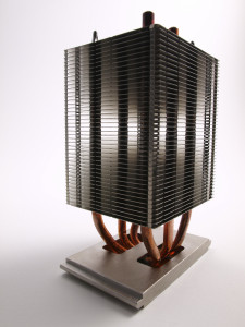
- Heat sinks are passive heat exchangers that can dissipate large amounts of heat into the surrounding environment by either natural or forced convection. To take full advantage you still have to get the heat from the power components and dissipate it into the atmosphere which may require close control of material properties and airflow. Heat sinks are designed to maximize the surface area in contact with the cooling medium. Air velocity, choice of material, protrusion design and surface treatment are factors that affect the performance of a heat sink. To be most effective both mass flow rate and turbulence need to be maximized. The effectiveness of a heat sink depends on the temperature difference between the heat sink itself and the adjacent air. If the air is warm (right against the fins) then the heat sink must run hotter than it would with cooler air against the fins. The most effective heat sinks are attached to the component using thermal interface materials that both fill air gaps and act as a high conductivity path.
4. Forced air cooling
- Forced-air cooling using a fan to blow air across hot components is very common and completely internal fans are used by many manufacturers. To be most effective the fan must blow air across the component to provide the best cooling; air leaving the fan blades is turbulent, and it swirls around vigorously as it leaves the fan blades. This allows the airflow to disrupt otherwise stagnant air therefore providing the maximum supply of cool air. If the fan is set to suck air across the surface the flow will be laminar, moving fastest in the centre, with comparatively little movement at the surface.
5. Water cooling
- Water is the best heat removal media known, with a specific heat of 4.1813 (J / (g·K)), it requires more energy to raise a gram of water by one degree C (or 1 Kelvin) than any other material. Consequently if extremely high power is the goal, a water cooled heat sink is an option to be considered. Provided the thermal resistance from the junction to the heat sink is minimized, a small heat sink with moderate water flow will remove large amounts of heat.
6. Heat pipes
- Heat pipes are most commonly used where a hot component must be cooled in a confined space. The heat pipe provides heat-transfer by combining both thermal conductivity and phase transition to efficiently manage the transfer of heat between two solid interfaces. A heat pipe is essentially two heat sinks, joined by a pipe; at the hot interface a liquid in contact with a thermally conductive solid surface turns into a vapor. The vapor then travels along the heat pipe to the cold interface and condenses – releasing the latent heat. The liquid then returns to the hot interface, and the cycle repeats. Newer versions make use of ‘micro-channels’ to dramatically increase the surface area at the hot end and allow the use of environmentally friendly coolants.
7. Other technologies – Two other technologies that may be of interest for cooling strategies are:
- Thermoelectrics: The most commonly used thermoelectric material is bismuth telluride (Bi2Te3). These materials provide the option by which either a temperature difference creates an electric potential or an electric potential creates a temperature difference. These phenomena are known more specifically as the Seebeck effect (converting temperature to current), Peltier effect (converting current to temperature), and Thomson effect (conductor heating/cooling). Thus localized cooling can be directly obtained but heat dissipation from the thermoelectric material may still be required.
- Piezo fans: Piezo-electric material produce changes in shape when subject to an applied voltage, or vice versa. When subject to an oscillating voltage an oscillating motion can be developed, that, when attached to structures that resonate at the applied frequency, can act as a fan for localized air flow thus enhancing local cooling.
In brief, options for reducing the temperature of devices and components require that additional paths with high thermal conductivity are added to increase dissipation of heat into the surrounding environment. This is most effectively obtained by modifying the materials of construction, adding heat sinks and increasing local air flow by natural or forced convection. The most commonly used of these approaches if the addition of heat sinks, further details on the design of effective heat sinks will be covered in the next Blog. In the meantime please feel free to contact us if you have questions about thermal analysis of electronics or feasibility studies in general, or if you would like to discuss thermal aspects of your application.

